Cam Design History
Here we describe some of the history of cam design starting about 1906. We have somewhat limited information on non-Ford cars, but an almost complete history of Ford Cams, including the lobe designs, throughout the flathead era, i.e. thru 1953. Some of this information on Ford cams has never been available outside the Ford Archives. We are indebted to George DeAngelis and Trent Boggess for obtaining copies of original Ford drawings from the archives. We believe it is useful to look at early cam timing and cam designs, since it exposes us to the widest range of engines. This discussion is divided into the following parts:
- Timing of Early Cams - general cam timing
- Ford Flathead Cam Lobe Design - 1913 to 1953
- Post 1950 Cam Design
Timing of Early Cams
It is obvious from reading Dykes that early engine designers were quite knowledgeable about cam timing and its influence on performance. Trent Boggess uncovered a report by a Ford engineer, August Degner, of a study of the Ford Model N (the Models N, R and S were similar and immediately preceded the Model T). They compared a cam with 205/217 intake and exhaust duration to one with 210/224. These had fairly tight, 108.5 and 109 degree, lobe separations. The shorter duration cam was retarded 0.5 degrees and the longer duration one was retarded 3.5 degrees. The conclusion of the study was that the long duration cam produced the highest horsepower (at 1400 RPM), while the shortest duration cam had better drivability. The shorter duration cam was selected.
The table below shows basic seat-to-seat timing numbers for Ford cars thru 1951 and selected cars thru 1920. For the early cars, there is quite a variation amongst the different car makers, but several trends are evident. All used a short intake duration, averaging 210 to 215 degrees. Most opened the intake valve after TDC. Most ran a dual pattern with exhaust duration approximately 20 degrees greater than the intake. Lobe separation angles were large, averaging 112 to 113. Most cams were run a few degrees retarded. Keep in mind that most of these engines did not turn very fast. The Model T developed 20 hp at 1,600 RPM. Even the OHC Stutz produced its peak 130 horsepower at only 3,000 RPM. We believe these numbers are the result of good engineering and tedious experimentation. These are the typical timing numbers that should be used for a low revving engine.
| Intake | Intake | Exhaust | Exhaust | Intake | Exhaust | ||||||
| open | close | open | close | seat | seat | Intake | Exhaust | Lobe | Advance | ||
| Cam | BTDC | ABDC | BBDC | ATDC | duration | duration | center | center | separation | deg | Reference |
| Model N Cams: | |||||||||||
| Test, best HP at 1400 | -7 | 37 | 37 | 7 | 210 | 224 | 112.0 | 105.0 | 108.5 | -3.5 | Trent Boggess |
| Test, best driveability | -7 | 32 | 37 | 0 | 205 | 217 | 109.5 | 108.5 | 109.0 | -0.5 | " |
| Model T Cams: | |||||||||||
| Stock 1912- | -16.8 | 41.5 | 41.5 | 6.3 | 204.7 | 227.8 | 119.2 | 107.6 | 113.4 | -5.8 | service bulletins |
| Stock 1913+ | -12.7 | 50.8 | 37.9 | 0 | 218.1 | 217.9 | 121.8 | 109.0 | 115.4 | -6.4 | original drawing |
| Other Cams | |||||||||||
| Auburn 6-39K | 0 | 33 | 67 | 0 | 213 | 247 | 106.5 | 123.5 | 115.0 | 8.5 | Dykes 1920 |
| Cadillac 57 | 0 | 46.7 | 46.7 | 0 | 226.7 | 226.7 | 113.4 | 113.4 | 113.4 | 0.0 | Dykes 1920 |
| Chevrolet 490 | -16 | 52 | 40 | 16 | 216 | 236 | 124.0 | 102.0 | 113.0 | -11.0 | Dykes 1920 |
| Chevrolet D | 0 | 56 | 46 | 10 | 236 | 236 | 118.0 | 108.0 | 113.0 | -5.0 | Dykes 1920 |
| Dodge | -10 | 35 | 45 | 8 | 205 | 233 | 112.5 | 108.5 | 110.5 | -2.0 | Dykes 1920 |
| Duesenburg (race) | -4 | 42 | 46 | 8 | 218 | 234 | 113.0 | 109.0 | 111.0 | -2.0 | Dykes 1920 |
| Hudson O | -7 | 42 | 55 | 8 | 215 | 243 | 114.5 | 113.5 | 114.0 | -0.5 | Dykes 1920 |
| Maxwell (race) | 0 | 32 | 69 | 13 | 212 | 262 | 106.0 | 118.0 | 112.0 | 6.0 | Dykes 1920 |
| Mercer | -5 | 55 | 70 | 15 | 230 | 265 | 120.0 | 117.5 | 118.8 | -1.3 | Dykes 1920 |
| Oldsmobile 45-A | -15 | 38 | 45 | 10 | 203 | 235 | 116.5 | 107.5 | 112.0 | -4.5 | Dykes 1920 |
| Oldsmobile 37-A | -17.3 | 38 | 42.3 | 7.3 | 200.7 | 229.6 | 117.7 | 107.5 | 112.6 | -5.1 | Dykes 1920 |
| Packard | -9 | 42.3 | 47.3 | 4 | 213.3 | 231.3 | 115.7 | 111.7 | 113.7 | -2.0 | Dykes 1920 |
| Stutz SOHC | -10 | 55 | 55 | 10 | 225 | 245 | 122.5 | 112.5 | 117.5 | -5.0 | Dykes 1920 |
| Willys Six 89 | -10 | 28 | 40 | 2.3 | 198 | 222.3 | 109.0 | 108.9 | 108.9 | -0.1 | Dykes 1920 |
| Average of above | -7.7 | 43.1 | 50.1 | 7.4 | 215.3 | 237.6 | 115.4 | 111.4 | 113.4 | -2.0 | |
| average of 114 cars | -9.5 | 37.0 | 50.0 | 9.0 | 207.5 | 239 | 113.3 | 110.5 | 111.9 | -1.4 | Dykes 1920 |
| Model A/B | |||||||||||
| Stock Model A | 8 | 48 | 51 | 5 | 236 | 236 | 110.0 | 113.0 | 111.5 | 1.5 | original drawing |
| Stock Model B | 8 | 56 | 56 | 8 | 244 | 244 | 114.0 | 114.0 | 114.0 | 0.0 | original drawing |
| Early V8/6 Cams: | |||||||||||
| Stock 32-36 (18-6250) | 9.5 | 54.5 | 57.5 | 6.5 | 244 | 244 | 112.5 | 115.5 | 114.0 | 1.5 | original drawing |
| Stock 37-48 (78-6250) | 0 | 44 | 48 | 6 | 224 | 234 | 112.0 | 111.0 | 111.5 | -0.5 | original drawing |
| Stock 49-51 (8BA-6250) | 5 | 44 | 48 | 3 | 229 | 231 | 109.5 | 112.5 | 111.0 | 1.5 | original drawing |
| Stock 49 Merc.8CM | 10 | 50 | 50 | 10 | 240 | 240 | 110.0 | 110.0 | 110.0 | 0.0 | original drawing |
| Stock 46 6 cyl 7HA | 11 | 41 | 48 | 10 | 232 | 238 | 105.0 | 109.0 | 107.0 | 2.0 | original drawing |
Ford Flathead Cam Lobe Design
The table above has only basic timing numbers, because that is all that is available for most of the engines. However, for most of the Ford cams we have the original drawings from the Ford archives. Many of the early cams give the description in terms of arc radius of curvature and centers. We have used this information to calculate detailed lift curve information. This gives cam design details that have not previously been available. The detailed calculations are summarized in the following table, while some of the specific designs are discussed below. Most of the columns in the table are self explanatory, but some are not. "Ramp Height" lists the lift at the end of the ramp, which is used to calculate the seat-to-seat duration. If the cam had no ramp, the valve lash is used. Only the seat-to-seat timing numbers were known previously. In the table, we have also tabulated the duration at 0.050 gross and 0.040 net lift. The 0.040 net numbers compensate for differences in valve lash (see What's wrong with 0.050 duration?). "Hole Size" lists the size of the cam bearing hole, and "Cam Size" is the diameter of the base circle plus twice the lift, i.e. the minimum size hole the cam will slide through. "Required Lifter" lists the minimum lifter diameter calculated from the maximum velocity, which can be compared to the listed actual lifter size. "Ramp Velocity" is the velocity at the ramp height. The maximum acceleration on the flank and maximum deceleration at the nose are also listed.
| Ramp | Duration | Duration | Duration | Hole | Cam | Lifter | Required | Ramp | Max | Min | |||||
| Cam | Number | Method | Lift | Lash (in/ex) | Height | Seat | 0.050 grs | 0.040 net | Size | Size | Size | Lifter | Velocity | Accel | Accel |
| Model T | 3 arc | 0.250 | 0.025 | 0.025 | 218.7 | 195.5 | 184.3 | 1.375 | 1.313 | 1 | 0.809 | 0.0036 | 0.00026 | -0.00019 | |
| Model A | A-6250 | 5 arc | 0.302 | 0.015 | 0.015 | 236.0 | 195.8 | 193.0 | 1.563 | 1.558 | 1.125 | 1.068 | 0.0000 | 0.00069 | -0.00023 |
| Model B Intake | B-6250 | 5 arc | 0.334 | 0.015 | 0.015 | 244.0 | 207.8 | 205.3 | 1.563 | 1.558 | 1.187 | 1.140 | 0.0000 | 0.00086 | -0.00023 |
| Model B Exhaust | B-6250 | 4 arc | 0.341 | 0.022 | 0.022 | 244.0 | 214.9 | 207.5 | 1.563 | 1.558 | 1.187 | 1.096 | 0.0017 | 0.00058 | -0.00023 |
| 1932-36 V8 | 18-6250 | 6 arc | 0.307 | 0.015 | 0.015 | 244.0 | 204.4 | 200.9 | 1.795 | 1.780 | 1 | 0.903 | 0.0000 | 0.00079 | -0.00025 |
| 1937-48 V8 Intake | 78-6250 | 6 arc | 0.307 | 0.011 | 0.015 | 224.0 | 197.1 | 194.6 | 1.795 | 1.780 | 1 | 0.914 | 0.0005 | 0.00149 | -0.00026 |
| 1937-48 V8 Exhaust | 78-6250 | 6 arc | 0.307 | 0.015 | 0.015 | 234.0 | 200.6 | 198.1 | 1.795 | 1.780 | 1 | 0.910 | 0.0005 | 0.00088 | -0.00024 |
| 1949-51 V8 Intake | 8BA-6250 | Triple Curve | 0.307 | 0.014 | 0.018/0.020 | 229.0 | 198.0 | 193.6 | 1.795 | 1.780 | 1 | 0.923 | 0.0005 | 0.00124 | -0.00026 |
| 1949-51 V8 Exhaust | 8BA-6250 | Triple Curve | 0.307 | 0.018 | 0.020 | 231.0 | 198.8 | 193.2 | 1.795 | 1.780 | 1 | 0.923 | 0.0005 | 0.00107 | -0.00026 |
| 1949-50 Mercury | 8CM-6250 | Triple Curve | 0.338 | 0.012/0.014 | 0.015 | 240.0 | 207.5 | 205.0 | 1.795 | 1.786 | 1 | 0.920 | 0.0005 | 0.00100 | -0.00026 |
| 1946-52 6 Cyl Intake | 7HA | Triple Curve | 0.350 | 0.014 | 0.015 | 232.0 | 205.2 | 202.9 | 1.950 | 1.920 | 1 | 0.969 | 0.0005 | 0.00147 | -0.00027 |
| 1946-52 6 Cyl Exhaust | 7HA | Triple Curve | 0.350 | 0.014 | 0.015 | 238.0 | 211.4 | 209.0 | 1.950 | 1.920 | 1 | 0.969 | 0.0005 | 0.00149 | -0.00025 |
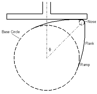
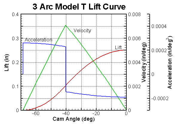
The illustration at the left is of a Model T cam lobe and lifter. Most early cam profiles were of the 3 arc harmonic type like this one. It is composed of three arcs: base circle with radius of 0.406 inches, nose with radius of 0.0313 inches and flank with radius of 1.260 inches. The lift curve is shown at right. The arcs are aligned so that velocity is continuous, but the acceleration curve contains jump discontinuities at the arc intersections. Each section of the curve is a trigonometric function. This curve has a total lift of 0.250. The seat-to-seat duration is 218.7 degrees at the valve lash of 0.025. The duration is 195.5 at 0.050 gross and 184.3 at 0.040 net.
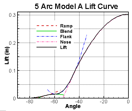
Simple three arc designs were common until about 1930. These profiles have no ramp, but Turkish describes how the method can be modified to include a ramp. For the Model A, Ford incorporated ramps by adding two additional arcs to the lobe. The graph below left shows the lift curve for the Model A with the various arcs extended to make them visible. The two additional arcs are labeled "Ramp" and "Blend". This curve has a ramp velocity of zero at 0.015 lift. The seat-to-seat duration (at 0.015) is 236 degrees, while the duration is 195.8 degrees at 0.050 and 193.0 at 0.040 net. The lift is 0.302.
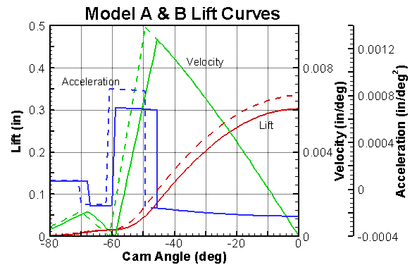
The graph below right compares the Model B intake (dashed lines) to the Model A cam (solid lines). The Model B cam had a similar design, but with more duration and lift. It's seat-to-seat duration is 244, while the duration is 207.8 at 0.050 and 205.3 at 0.040 net. The lift is 0.334. The Model B had a different exhaust lobe (dual pattern cam). For the exhaust lobe, the "Blend" arc was eliminated to give only 4 arcs, with a ramp velocity of 0.0017 at the valve lash of 0.022. The seat-to-seat duration is 244 degrees (at 0.022), duration is 214.9 at 0.050 gross and 207.5 at 0.040 net. The exhaust lift is 0.341. The maximum velocity for the Model A cam required a 1.125 inch diameter lifter, the Model B velocity was even higher requiring a 1.187 diameter lifter.
 The
use of large diameter lifters was not a problem in the four cylinder
engines, but the flathead V8 only had room for a one inch diameter lifter.
With a conventional design, the lifter diameter would have imposed a
reduction of lift. To avoid this problem, Ford engineers
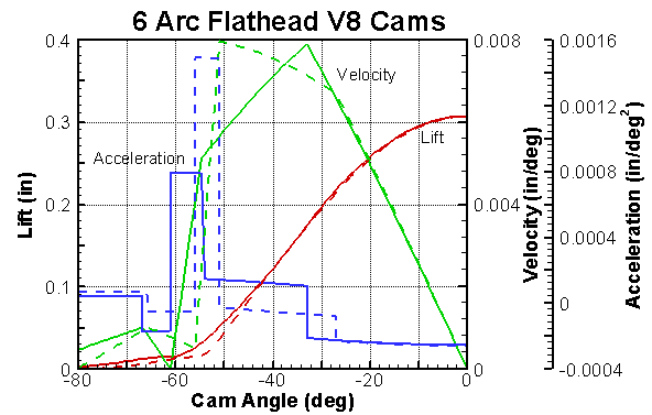
created a clever 6 arc design. An additional low acceleration
arc was added on the flank. The extra arc reduced the variation
in velocity, so the 6 arc design was somewhat similar to a
Triple Curve Design which
was not published until 1934. The lift curve for two of these
6 arc designs is shown at the right. The solid lines are for
the 1932-36 cam (18-6250), while the dashed lines are for the intake
of the
1937-48 cam (78-6250). The earlier V8 cam had a zero ramp
velocity like the A and B cams, while the later one had a more
conventional ramp velocity of 0.0005 in/deg. The lift is 0.307
inches for both cams. The later cam is more aggressive (see
What is an Aggressive Cam?) with a
quicker opening. There is little difference between the lift
curves above 0.100 lift. The maximum acceleration rate of
0.0015 in/deg2 is as high as any of the flathead cams.
The later cam was dual pattern with a less aggressive exhaust lobe
that had a few degrees more duration and the same lift.
The
use of large diameter lifters was not a problem in the four cylinder
engines, but the flathead V8 only had room for a one inch diameter lifter.
With a conventional design, the lifter diameter would have imposed a
reduction of lift. To avoid this problem, Ford engineers
created a clever 6 arc design. An additional low acceleration
arc was added on the flank. The extra arc reduced the variation
in velocity, so the 6 arc design was somewhat similar to a
Triple Curve Design which
was not published until 1934. The lift curve for two of these
6 arc designs is shown at the right. The solid lines are for
the 1932-36 cam (18-6250), while the dashed lines are for the intake
of the
1937-48 cam (78-6250). The earlier V8 cam had a zero ramp
velocity like the A and B cams, while the later one had a more
conventional ramp velocity of 0.0005 in/deg. The lift is 0.307
inches for both cams. The later cam is more aggressive (see
What is an Aggressive Cam?) with a
quicker opening. There is little difference between the lift
curves above 0.100 lift. The maximum acceleration rate of
0.0015 in/deg2 is as high as any of the flathead cams.
The later cam was dual pattern with a less aggressive exhaust lobe
that had a few degrees more duration and the same lift.
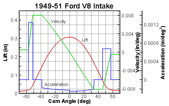 In
the 1940's Ford abandoned cams designed from arcs and started using
the Triple Curve Design Method.
The Cam Design page
describes this method and shows the 1949-50 Mercury (8CM) cam as an
example. The graph at the left shows the intake for the
1948-51 Ford (8BA) cam. It had an unusual design. Both
the intake and exhaust lobes were asymmetric. In addition to
the normal discontinuities in acceleration, this cam also had a
discontinuity at the nose. The radius of curvature changes
from 0.150 to 0.060 at the center. The flank acceleration on the
closing side is about half that on the opening side. The ramp
height is 0.018 on the opening side and 0.020 on the closing side.
With these ramp heights the seat-to-seat duration is symmetrical,
but the 0.050 duration is 100.9 (opening) and 97.1 (closing) to give
198 total. It's surprising that the only flathead cams with
less duration were the Model T and Model A cams (based on the 0.040
net duration). The cams with the highest duration were the
Model B and 1949-50 Mercury. The Mercury cam with its greater
lift and duration should give a mild boost in high RPM performance
compared to the other V8 cams. Some of the contemporary books
(see References) give incomplete timing numbers for 1952-53 Ford and
Mercury V8 cams. We do not have the original drawings for
these cams or the cams for the V8-60 and early 1941 six cylinder
engines.
Post 1950 Cam Designs
Harmonic cam profiles and triple curve designs were common to many of the auto makers. Hollingsworth and Hodges describes the use of both methods by the English car makers. The most important deficiency of these methods is they have abrupt jump discontinuities in acceleration, i.e. infinite jerk. Infinite jerk tends to trigger vibrations in the valve train. Most engines prior to 1950, especially those in the US, were flatheads (side valve, L head) and relatively slow turning, < 4500 RPM. A flathead valve train is very stiff. Infinite jerk is not a problem with these engines. When higher revving OHV engines appeared cam profiles with infinite jerk fell from favor (see Jerk is it Important?).
Prior to 1950, Chevrolet, Buick and Oldsmobile were the only major US companies with OHV engines, and they were not particularly high revving engines. Overhead valve engines were more popular with overseas car makers. Unfortunately, we have little information about their cam designs. Turlay states that in the 1930's cam designs at Buick were primarily by hand drawn graphical methods. Hollingsworth and Hodges state that graphical methods were also used at the English company Standard Triumph. Most likely, the Triumph TR4 cam shown on the Cam Design page was constructed graphically. Turkish (1946) describes some techniques for graphical construction by modification of harmonic or triple curve profiles. With this method the acceleration curve is drawn on a large scale and the negative and positive acceleration areas are carefully balanced. The curves are then numerically integrated to obtain velocity and again to obtain lift. Turkish also describes other techniques for smooth profiles using a combination of two simple analytic functions, one for the acceleration flank and one for the nose. In the days before computers, the development of smooth cam profiles was very tedious.
The Polydyne Method is another smooth cam profile method. This term was coined by Thoren, et al. in 1952 to describe the method originated by Dudley in 1948. This method uses a simple valve train dynamic model to determine the lobe shape that will produce a specified dynamic profile. The cam must be designed for a specific engine speed and can perform poorly at other speeds. This method was apparently tried by many of the car companies, but was not adopted by any. The method uses an incomplete polynomial to specify the profile (see Cam Design).
By the early 1950's most of the US car makers were working on OHV engines, consequently many cam design concepts underwent radical change. On March 5, 1953 an SAE technical meeting in Detroit (published in SAE Transactions, vol. 61, see References) had a very interesting session on camshafts and valve trains. It featured speakers from the major companies and universities and some interesting discussions which revealed the thinking at the time. For the first time, the results of valve train dynamic model calculations were presented in two back to back papers. Philip Barkan presented his classic paper on valve train dynamics. He solved a single degree of freedom (SDOF) model using a mechanical desk calculator and matched it to experimental data. His concepts regarding the importance of Coulomb friction have been born out by later studies. Another SDOF model was solved by Roggenbuck (Ford Motor Co.) using an early analog computer. These SDOF models treat the valve spring as an ideal massless spring which cannot surge. For the first time, these papers indicated the valve train is the most important component and that spring surge is of secondary importance. To study the importance of acceleration smoothness and jerk, both Roggenbuck and Horan presented the results of calculations with various flank acceleration curves. Roggenbuck favored a constant acceleration curve (with infinite jerk), while Horan favored a smooth parabolic curve. None of these results were strongly conclusive regarding the importance of jerk.
The discussion of the papers centered on the importance of spring surge and jerk. Turlay described some of the experiences at Buick in the 1930's. Their method of cam design and testing was primarily experimental. They found that very subtle changes in the smoothness of the cam made profound changes in valve train performance. The concerns about the importance of jerk can be traced to the presentations and discussions at this conference.
Prior to this conference, spring surge was thought to be the dominate cause of valve train problems. The papers by Barkan and Roggenbuck clearly demonstrated this was not the case. Later papers (look in References for Pisano and Freudenstein, Hanachi and Freudenstein, and Phlips, et al.) have confirmed that spring dynamics do play a role in the performance of the valve train, but it is of secondary importance. The current day popular concept regarding spring surge have not yet caught up (see Spring Surge - Catastrophe or Not?). The Valve Train Dynamics page discusses this subject in greater detail.
From the early 1950's, cam design methods with infinite jerk (harmonic, triple curve, etc.) were abandoned and incomplete polynomial methods became the most popular lobe design method.