Cams and Engine Performance
Cam Basics describes the basic terminology used in the specifications of a camshaft. Here we discuss how these camshaft specifications influence the performance of an engine. This discussion is divided into the following parts:
- Intake Duration
- Other Timing Events - advance, duration and lobe separation
- Cam Lift
- Opening and Closing Rate
- Summary
Intake Duration
Let's first talk about the intake valve. The intake is much more critical than the exhaust because intake flow is driven only by atmospheric pressure (unless you are supercharging). Exhaust flow is driven by the much higher pressures created by combustion.
You might think that the intake valve should open instantaneously at TDC and close instantaneously at BDC, i.e. at the beginning and end of the intake stroke. This would give a duration of 180 degrees. This would be a good choice of timing for a very slow turning engine. However, there are a couple of problems for real engines. First, the valves can not be opened and closed instantaneously, so it is better to start opening the intake valve before TDC and close is a bit after BDC. Second, air is compressible and has inertia, so for faster engine speeds more air and fuel will be captured if the intake valve is closed later. The higher the engine speed the later it should be closed.
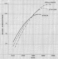 We
can immediately see that the cam must be designed for a certain
engine speed. Consequently, the camshaft design invariably
offers tradeoffs between high RPM performance and low RPM
performance. Engineers were familiar with these tradeoffs and
the performance implications as far back as 1910. The graph at
left (click to enlarge) is for a flathead Ford V8 from a
classic book by Roger Huntington. The approximate
intake duration for the cams in the graph are: (1) stock - 230
degrees seat-to-seat, 200 at 0.050, (2) 3/4 race - 260 seat-to-seat
and 220 at 0.050, and (3) full race 270 seat-to-seat and 230 at
0.050. Huntington did not recommend the full race cam for
street use because it produces so little power at low RPM, causing
poor drivability. (See
What's a 3/4 Race Cam?)
In order to gain power with a high performance (longer duration) camshaft, you must have an engine which is capable of reaching the higher RPM levels. For example, no matter how much duration you have, a stock Model T motor is never going to turn 5,000 RPMs. To achieve higher engine speeds you must have a head and manifold that will flow freely and a high enough compression ratio.
As an example, a stock Model T has a 4:1 compression ratio, poor air flow and a poor head design. Several years ago, we discovered that all of the reground camshafts available were too big, i.e. too much duration. This is called overcamming an engine - a very common mistake when building an engine (see Monroe). One dyno test showed that a stock cam (218 degrees duration) produced the same peak horsepower and up to 15% more midrange power. The midrange power is extremely important for driveability with only two forward gears.
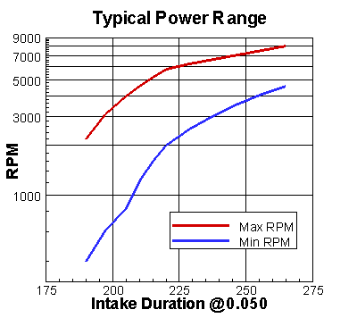 There
are many engine characteristics which will effect your camshaft
selection, so there is no single best camshaft. The graph at the
right was created after review of many data sources in combination
with the data given by Hammill. It
shows the typical RPM range as a function of the intake valve
duration at 0.050 lift. See "What's Wrong
with 0.050 Duration?" for a discussion of duration measurement
standards.
The camshaft that produces the highest peak horsepower is usually not the best camshaft. For example, the graph shows that a cam with 255 degrees duration comes on at about 4,000 RPM. For a street application, you might have to rev considerably and slip the clutch to get going. True, a long duration race cam produces more power, but drivability suffers. A high performance cam invariably produces its power in a narrower RPM range (the two curves in the graph are converging). This means it will require more gear shifting to remain in the power band when climbing hills or when accelerating out of turns on a road course. Normally, the best camshaft will produce peak horsepower near the upper-middle of the planned RPM operating range.
The first step when selecting a camshaft is to make an honest appraisal of your engine (compression ratio, head flow, etc.) and your driving plans (street, road race, etc.).
Other Timing Events
So far, we've talked only about the intake valve duration. The overall cam timing can be characterized using four opening and closing parameters. We will assume these events are measured at 0.050 lift or some other uniform standard. We will discuss the importance of seat-to-seat timing below under Opening Rate. The events are listed here in their usual order of importance (see Monroe):
- Intake closing angle
- Intake opening angle
- Exhaust opening angle
- Exhaust closing angle
The first two events determine the intake duration (closing minus opening), which is built into the camshaft. The exhaust opening and closing are the next most important parameters. The exhaust lobe is fixed relative to the intake lobe by the lobe separation angle. All of the events can be shifted by advancing or retarding the cam during installation.
Rather than the four timing events above, we prefer to use the following equivalent set of parameters:
- Cam advance
- Intake valve duration
- Exhaust valve duration
- Lobe separation angle
Conversion between these above two sets of specifications is easily accomplished using the Cam Calculator on the Download page.
The effect these parameters have on performance is easily understood if you remember that intake closing is the most important event. Because of gas compressibility and inertia, closing the intake valve sooner produces more low end power and torque and less power at high RPM. Closing the intake valve later produces more high end power at the expense of the low end. This explains why an increase in the intake valve duration moves the power band to higher engine speeds. When the cam is advanced, the intake valve closes sooner, so you get more power at the low end. Reducing the lobe separation angle also causes the intake valve to close sooner, so you again get more low end power.
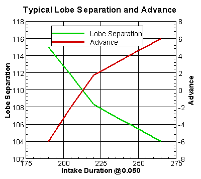 There
are other more subtle characteristics which are easily understood if
you remember the relative importance of the timing events. The
graph at right was constructed after review of many sources, e.g. Hammill and
Dykes (see References
and History).
As the intake valve duration is increased, the cam should normally
be advanced and the lobe separation should be reduced slightly.
Making small changes in the advance and lobe separation keeps the
most important events (intake closing and exhaust opening) near
their optimum values. There will be larger changes in the less
important intake opening and exhaust closing. This graph gives
general trends, specific engine characteristics (.e.g flow
characteristics and Rod
Length) will influence the best choice of the timing events.
For design purposes, we prefer to use the second set of four timing parameters, because the first one (advance) can be set based on dyno performance after the cam is installed. For some engines you can purchase a vernier sprocket or gear to make setting the advance easy. In other cases, you may have to redrill dowel pin holes, keyways, or use offset keys or dowel pins. If you are creative, there is always a way to adjust the advance without grinding another camshaft. The intake and exhaust duration and lobe separation are ground into the cam and must be set based on performance experience
When designing a camshaft, the most important decision is the selection of intake duration. Generally, there will be some experience with other cams for similar engines. In the worst case, a value can be selected from the graph above using the desired RPM range. Generally, the exhaust duration is no more than ten degrees greater than the intake duration. The lobe separation angle is of lesser importance and as a worst case it can be estimated from the graph above. The more information that is available the better the estimates for these parameters. The graphs give "typical" values which can be used as a starting point in the absence of other data.
Cam Lift
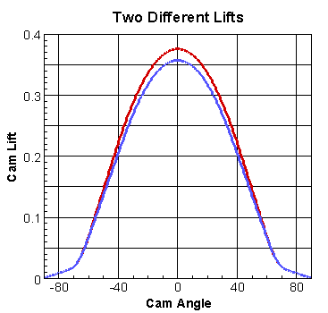 The
intake and exhaust lift are the most important parameters after the
four main timing events. For this discussion, we assume that
the four timing parameters have been specified at 0.050 lobe lift,
so the importance of lift is considered in this context.
There is no downside to lift. If there are no clearance issued involved, more lift is always better. It is easy to get more lift if you increase the duration, but here we assume that the duration has already been specified. Duration is more important than lift, so you never want to sacrifice duration for lift.
Consider the two lift curves at the right. Both have a duration of about 250 degrees at 0.050. In fact, the curves are identical below 0.050 lift. The difference in the maximum lift is only about 0.020, about 0.380 versus 0.360. If we assume these cams will be installed with a rocker ratio of 1.5, both will produce a valve lift in excess of 0.500. Some would argue that little additional flow occurs when you increase the valve opening from say 0.500 to 0.530, so why would you want a cam with this much lift? It is true that flow tends to level out at high lifts; however, the higher lift cam reaches intermediate lifts quicker, so the valve is open longer at these intermediate lifts. For the two cams shown, the duration at a lift of 0.250 differs by 11 crank degrees. Besides, once you've got the valve train moving, slowing it down abruptly to reduce the lift will trigger vibrations and require stiffer valve springs to counteract the deceleration. Constraining the lift makes sense only when there are clearance issues. In most cases the additional flow throughout the heart of the lift event is significant and it translates directly into improved performance.
Opening and Closing Rate
The ideal cam would be one that opens and closes the valve instantaneously at the optimum crank angles. This ideal cam would give a square lift curve. Instantaneous opening is not possible because it would require infinite acceleration of all the mass in the valve train and would lead to infinite forces on the valve train components. However, we should keep the ideal lift curve in mind and try to open the valve as quickly as possible. Harvey Crane's website has a page which discusses this issue. He uses the term intensity to measure the quickness of the cam opening and closing. Substituting the term "quicker opening" for "smaller intensity", Crane states, "In practical terms if two cams with similar lobe designs have the same duration at 0.050 lift, maximum torque and horsepower will be almost identical. However, the cam with the quicker opening will have a smoother idle, better off-idle response, superior low speed drivability and a broader power curve." Bakoni and Hollingsworth and Hodges also describe the advantages of quick opening cams.
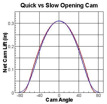 Consider
the two lift curves in the graph at the right. The valve lash
of 0.010 has been subtracted from these curves so that net cam lift
is plotted. These curves are an exaggeration of the problem we
frequently encounter with "performance" camshafts. Both cams
have a duration of 250 at 0.050 (0.040 net) and a gross lift of
0.320. For this discussion, we want to concentrate on the
difference between the curves for lifts below 0.040, i.e. the
opening and closing. The differences may not look significant,
but the seat-to-seat duration is 299 degrees for the quick opening
cam (red curve) and 333 for the slow opening cam (blue curve).
The slow opening cam has 34 degrees more overlap. For a 110
lobe separation, that translates into a whopping 113 degrees of
overlap. The quick opening cam will have all the benefits
cited by Crane. Actually, it's impossible to make the two lift
curves the same above 0.040. The quick opening cam has 9
degrees more duration at 0.150. This increased breadth of the red curve
above 0.040 will also contribute to
better performance. The cam with the red lift curve will
produce a broader power band by
improving the low end performance of the engine, with a slight
increase in the high end performance. As stated above, a high
performance cam will invariably sacrifice low end power and torque
for high RPM power. The sacrifice of low end performance is
reduced using a quick opening cam.
Note: Crane defines minor intensity to be the difference in duration between 0.050 lift and 0.010 lift. The minor intensity of these examples are (299 - 250) = 49 degrees for the quick opening cam and (333 - 250) = 83 degrees for the slow opening cam.
Summary
- The most important cam design parameters are the four timing events or equivalently the advance, intake and exhaust duration and lobe separation angle.
- Once the four timing parameters are established, the cam should be designed for maximum lift
- A quick opening and closing cam will provide better low end performance than one that is slower opening.
The trick is to know what values to use for the timing parameters. Although we know general ranges of values and trends, the timing numbers must be established from performance experience. Next, we must know how to design the cam for maximum lift and quick opening. We discuss these aspects of a design on the Cam Design page. For some additonal discussion of cam quality, look at What's Wrong with Area Under the Lift Curve?